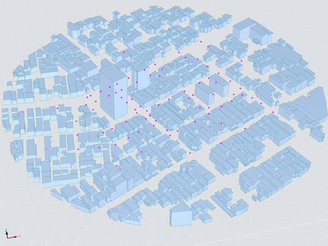
O Instituto de Arquitectura do Japão (AIJ) apresentou uma série de cenários de referência bem conhecidos para a simulação de vento.
O seguinte artigo é sobre o "Caso E - um complexo de edifícios numa área urbana real com uma densidade alta de edifícios na cidade de Niigata".
A seguir, o cenário descrito é simulado no RWIND2 e os resultados são comparados com resultados simulados e experimentais da AIJ.
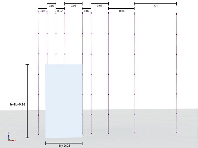
O Instituto de Arquitectura do Japão (AIJ) já foi considerado um Benchmark-Szenarien für Windsimulation vorgestellt.
Der Nachfolgende Beitrag dreht sich dabei um den "Caso A - torre com a forma de 2:1:1".
Im Folgenden wird das beschriebene Szenario in RWIND2 nachgebildet und die Ergebnisse mit den simulierten und der experimentellen Resultate des AIJ verglichen.
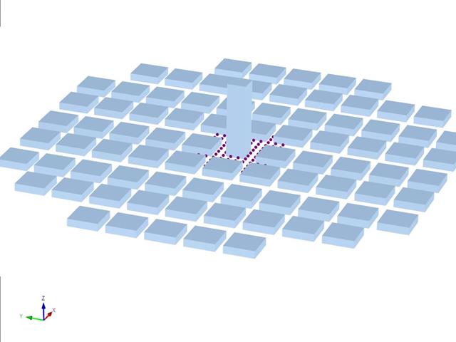
O Instituto de Arquitectura do Japão (AIJ) apresentou uma série de cenários de referência bem conhecidos para a simulação de vento.
O seguinte artigo trata do "Caso D - Torre entre quarteirões".
A seguir, o cenário descrito é simulado no RWIND2 e os resultados são comparados com resultados simulados e experimentais da AIJ.
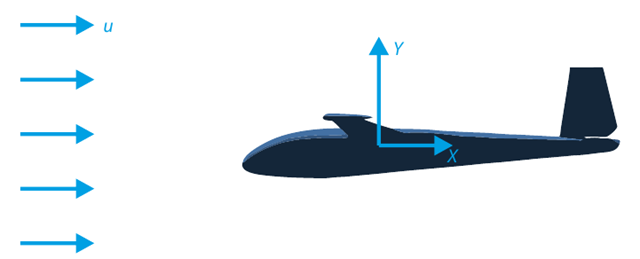
Um dos objetivos deste exemplo de verificação é analisar o fluxo de fluido em torno do planador. A tarefa consiste em determinar o coeficiente de arrasto e o coeficiente de sustentação em relação ao ângulo de ataque. Estes coeficientes também podem ser introduzidos no diagrama da curva polar de arrasto. O ângulo limite para o fluxo de fluido laminar em torno do perfil da asa também pode ser determinado a partir do campo de velocidades. O modelo CAD 3D disponível (ficheiro STL) foi utilizado no RWIND 2.
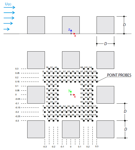
O exemplo de verificação descreve cargas de vento em várias direções do vento num modelo de um grupo de edifícios. The model consists of eight cubes. The velocity fields obtained by the RWIND simulation are compared with the measured values from the experiment. The experimental data are measured using a thermistor anemometer in the wind tunnel.
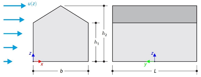
This verification example compares wind load calculations on a duopitch roof building using the ASCE 7-16 standard and using CFD simulation in RWIND Simulation. O edifício é definido conforme o esboço e o perfil da velocidade do fluxo contido na norma ASCE 7-16.
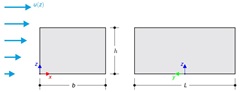
This verification example compares wind load calculations on a flat roof building using the ASCE 7-16 standard and using CFD simulation in RWIND Simulation. O edifício é definido conforme o esboço e o perfil da velocidade do fluxo contido na norma ASCE 7-16.
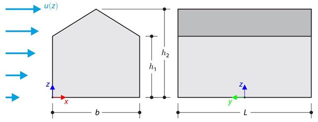
No exemplo de verificação, o cálculo de cargas de vento num edifício com cobertura de duas águas utilizando a norma EN 1991-1-4 é comparado com uma simulação CFD no RWIND Simulation. The building is defined according to the sketch, and the inflow velocity profile is taken according to the standard EN 1991-1-4.
No exemplo de verificação, o cálculo da carga de vento num edifício com cobertura plana utilizando a norma EN 1991-1-4 é comparado com uma simulação CFD no RWIND Simulation. The building is defined according to the sketch, and the inflow velocity profile is taken according to the standard EN 1991-1-4.
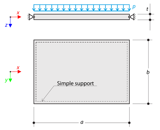
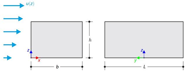
A thin rectangular orthotropic plate is simply supported and loaded by uniformly distributed pressure. The directions of axes x and y coincide with the principal directions. Determine a flecha máxima do painel, sem considerar o peso próprio.
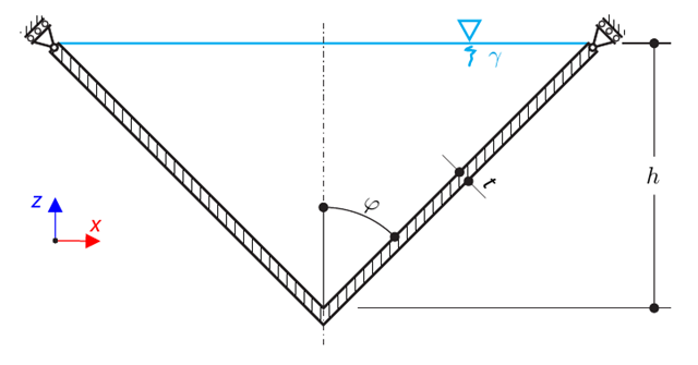
Um recipiente cónico de parede fina está cheio de água. Thus, it is loaded by hydrostatic pressure. While neglecting self-weight, determine the stresses in the surface line and circumferential direction. The analytical solution is based on the theory of thin-walled vessels. This theory was introduced in Verification Example 0084.
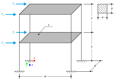
Este exemplo serve para ilustrar o plano. The application is shown on a two-story structure. The structure is loaded by means of lateral forces according to Figure 1. Determine the maximum deflection of the structure ux in the direction of the loading forces using both the diaphragm constraint and the plate model of the floor.
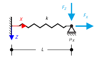
O objetivo deste exemplo é demonstrar um processo irreversível causado pelo atrito. After the loading and unloading, the end-point is in a different position than where it was at the beginning. Determine the movement of the node in the X direction.
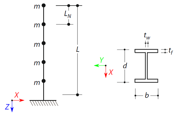
É definida uma viga em consola com uma secção de viga em I de comprimento L. The beam has five mass points with masses m acting in the X-direction. The self-weight is neglected. The frequencies, mode shapes, and equivalent loads of this 5-DOF system are analytically calculated and compared with the results from RSTAB and RFEM.